P25C4 Brake Booster Temperature Sensor Circuit: Meaning, Causes, Symptoms & Fix
P25C4 means the vehicle has detected a fault in the brake booster temperature sensor circuit. The problem may be a failed temperature sensor, damaged wiring, poor power or ground, connector corrosion, or an issue inside an electrically assisted brake booster or vacuum pump assembly. Because brake assist can be affected, this is a code to diagnose promptly rather than clear and ignore.
This is an informational search query: most drivers want to understand the code, judge whether the vehicle is safe, and identify the correct repair before replacing expensive brake components. The code definition is standardized at a general level, but the exact sensor location, expected voltage, and repair procedure vary by vehicle manufacturer and braking system.
What Does P25C4 Mean?
P25C4 is a diagnostic trouble code related to the brake booster temperature sensor circuit. The electronic brake control module, powertrain control module, or another related control unit monitors temperature feedback to protect the brake booster, electric vacuum pump, or integrated electro-hydraulic actuator from overheating.
On some vehicles, the sensor is built into the brake booster and cannot be replaced separately. On others, it may be part of an electric vacuum pump, brake actuator, or a short sensor harness. That difference matters: replacing a brake booster without checking the circuit can turn a wiring fault into an unnecessary, costly repair.
Common Causes of P25C4
- Failed brake booster temperature sensor or thermistor
- Open, shorted, or high-resistance wiring in the sensor circuit
- Loose, bent, pushed-back, or corroded connector terminals
- Water intrusion near the brake booster, vacuum pump, or control module
- Poor ground or unstable reference voltage
- Damaged wiring caused by battery work, engine repairs, or contact with hot components
- Overheating of the electric brake booster or vacuum pump
- Low system voltage, weak battery, or charging-system instability
- Software or calibration problems in the brake control module
- An internal failure of the brake booster or integrated actuator
A particularly common real-world mistake is blaming the sensor after seeing an implausible temperature reading. If the scan tool shows -40°F or -40°C, the circuit is often open. A reading that is extremely high, such as 250°F or higher on a cold vehicle, may indicate a shorted thermistor or a reference-voltage problem. These values are useful clues, but the manufacturer’s wiring diagram and specifications should decide the diagnosis.
Symptoms of a P25C4 Fault
The symptoms depend on whether the vehicle uses a conventional vacuum booster, an electric vacuum pump, or a fully integrated electronic brake system. Some vehicles store P25C4 with no obvious driving symptom, while others enter a reduced-assistance mode.
- Brake warning, ABS, ESC, or electronic parking brake warning lights
- “Service Brake System” or “Brake Assist Unavailable” message
- Hard brake pedal or increased pedal effort
- Electric vacuum pump running too often or for unusually long periods
- Reduced or inconsistent power-brake assistance
- Longer stopping distance, especially during repeated stops
- Stored communication or low-voltage codes alongside P25C4
- Intermittent symptoms that appear after rain, washing, or extended driving
A hard pedal does not prove that the booster temperature sensor itself has failed. It can also result from a vacuum leak, a failing pump, a brake actuator problem, or a loss of electrical power. If the pedal suddenly becomes unusually hard, stop driving in traffic and have the braking system inspected.
How to Diagnose P25C4 Correctly
1. Check all stored and pending codes
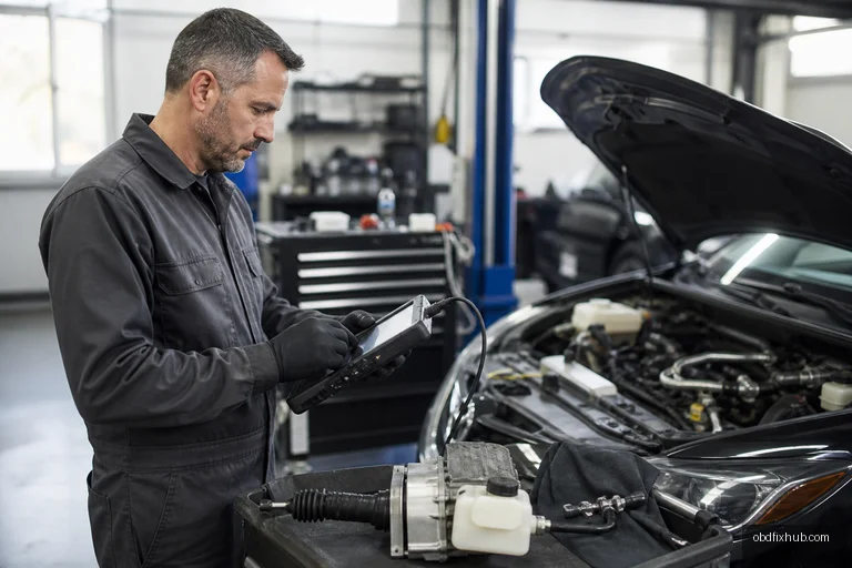
Use a scan tool that can access the ABS or brake control module, not only the generic engine computer. Record freeze-frame data, battery voltage, vehicle speed, brake pedal status, and any related codes before clearing anything. Low-voltage codes, pump performance codes, and module communication codes may identify the underlying problem.
2. Inspect the brake booster area
Locate the booster, electric vacuum pump, or brake actuator using the vehicle service manual. Look for wetness, green corrosion, damaged loom tape, melted insulation, and harnesses pulled tight against brackets. Pay special attention to areas disturbed during battery replacement, engine work, or windshield and cowl repairs.
3. Compare live temperature data
With the vehicle completely cold, compare the brake booster temperature PID with ambient temperature and, if available, other under-hood temperature readings. A sensor that reports an extreme value immediately after a cold soak is more suspicious than one that rises gradually with component temperature. Repeat the check while gently moving the harness; a changing reading often points to a poor connection or broken conductor.
4. Test power, ground, and signal circuits
Do not use resistance testing on a live circuit. With the ignition off and the connector disconnected, follow the wiring diagram to check continuity, short-to-ground, short-to-power, and terminal tension. With the circuit powered, verify the reference voltage and ground under load. A ground may look acceptable with a meter but fail when the pump or actuator operates, so a voltage-drop test is more reliable than a simple continuity check.
5. Test the sensor against temperature
Many booster temperature sensors are thermistors, meaning their resistance changes as temperature changes. The resistance curve is not universal: one vehicle may use an NTC sensor while another system uses a different configuration. Test it only against the manufacturer’s temperature-versus-resistance chart. Never apply uncontrolled heat directly to the sensor or use a heat gun near brake fluid, plastic components, or wiring.
6. Confirm the repair
After repairing the wiring or replacing the approved component, clear the codes and perform the required brake-system self-test or calibration. Then road-test the vehicle in a safe area while monitoring brake assist, warning lights, and live data. If the code returns only after the booster becomes warm, the fault may be thermal or internal rather than a simple open circuit.
How Is P25C4 Fixed?
The correct repair depends on the test results. Possible repairs include cleaning or replacing terminals, repairing a damaged section of harness, restoring a module ground, replacing a temperature sensor, updating control-module software, or replacing the electric vacuum pump or brake booster assembly.
- Connector problem: Repair terminal tension or corrosion; do not merely spray cleaner and reconnect a loose terminal.
- Wiring fault: Use sealed splices and route the repaired harness away from exhaust heat and moving parts.
- Sensor failure: Replace the sensor if the service procedure allows it; otherwise replace the specified integrated component.
- Low voltage: Test the battery, charging output, grounds, and voltage during brake-pump operation.
- Internal actuator failure: Follow the manufacturer’s replacement, bleeding, coding, and calibration procedure.
Brake systems with electronic boosters may require a scan-tool bleed, actuator initialization, or steering and stability-control calibration after component replacement. A repair that leaves air in the hydraulic system or skips calibration can create a new safety problem even when P25C4 no longer appears.
Can You Drive With P25C4?
If the brake pedal feels normal and no brake-assist warning is present, a short drive to a repair facility may be possible, but the fault should still be addressed quickly. Do not continue driving if the pedal is hard, braking assistance is intermittent, warning messages appear, or stopping distance has increased. In those cases, arrange a professional inspection or tow the vehicle.
Before driving, check the brake fluid level, confirm that the pedal is firm, and test the brakes at very low speed in a safe location. This is only a basic safety check, not a substitute for diagnosis.
Frequently Asked Questions
Is P25C4 a serious code?
It can be serious because the monitored component supports brake assistance or protects an electronic brake system. The severity depends on the vehicle’s design and current symptoms, but a hard pedal or brake warning requires immediate attention.
Can a weak battery cause P25C4?
Yes. Low voltage can create false or secondary sensor and module faults, especially when an electric vacuum pump or brake actuator starts. Test battery voltage and charging performance before replacing the booster.
Where is the brake booster temperature sensor located?
It may be integrated into the brake booster, electric vacuum pump, brake actuator, or its connector harness. Use the vehicle-specific service information because location and replacement access vary significantly.
Can I clear P25C4 myself?
You can clear the code with a capable scan tool, but clearing it does not repair the fault. If the circuit remains defective, the code will return, and a brake-system warning may reappear during operation.
Should I replace the brake booster immediately?
No. First verify the sensor signal, reference voltage, ground, wiring, connector condition, and system voltage. The booster should be replaced only when testing confirms an internal fault or the manufacturer specifies the sensor as an inseparable part of the assembly.
Final Takeaway
P25C4 points to a brake booster temperature sensor circuit problem, not automatically to a failed brake booster. Start with a full module scan, inspect the connector and harness, compare live temperature data on a cold vehicle, and test the circuit using the manufacturer’s specifications. If brake assist is reduced or the pedal feels hard, stop driving and have the vehicle professionally inspected.